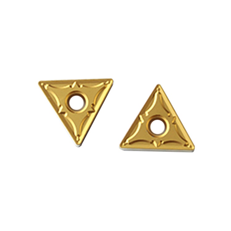
Carbide blade wear and edge chipping are common phenomena. When the carbide blade wears, it affects the workpiece processing accuracy, production efficiency, workpiece quality, etc.; when the operator observes blade wear, he should promptly respond to the problem. The machining process is carefully analyzed to identify the root causes of blade wear. It can be analyzed from the following aspects:
1. Flank surface wear
Flank wear refers to the abrasion loss of the tool flank below the cutting edge of the carbide insert and immediately adjacent to it; the carbide particles in the workpiece material or the work-hardened material rub against the insert, and small pieces of Coating peeling and blade friction; the cobalt element in the carbide blade eventually breaks away from the crystal lattice, reducing the adhesion of the carbide and causing it to peel.
How to judge flank wear? There is relatively uniform wear along the cutting edge, and occasionally peeling workpiece material adheres to the cutting edge, making the worn surface appear larger than the actual area; some alloy blades appear black after wear, and some blades appear shiny after wear. Bright; black is the bottom coating or the base of the blade displayed after the surface coating peels off.
Countermeasures include: first checking the cutting speed, recalculating the rotation speed to ensure its accuracy, and reducing the cutting speed without changing the feed;
Feed: Increase the feed per tooth (the feed must be high enough to avoid pure wear caused by small iron chip thickness);
Blade material: Use a more wear-resistant blade material. If you are using an uncoated blade, use a coated blade instead; check the blade geometry to determine whether it is processed on the corresponding cutter head.
2. Broken edge
Flank chipping is a condition that causes insert failure when small particles of the cutting edge are flaked off rather than being abraded by flank wear. Flank chipping occurs when there are changes in impact loads, such as in interrupted cuts. Flank chipping is often the result of unstable workpiece conditions, such as when the tool is too long or the workpiece is insufficiently supported; secondary cutting of chips can also easily cause chipping. Countermeasures include: reducing the tool protrusion length to its minimum value; selecting a tool with a larger relief angle; using a tool with a rounded or chamfered edge; selecting a tougher cutting-edge material for the tool; reducing the feed speed; Increasing process stability; improve chip removal effect and many other aspects. Rake face spalling: Sticky materials can cause material rebound after cutting, which may extend beyond the relief angle of the tool and create friction between the tool's flank surface and the workpiece; friction can cause a polishing effect that may It will lead to work hardening of the workpiece; it will increase the contact between the tool and the workpiece, which will cause the heat to cause thermal expansion, causing the rake face to expand, resulting in rake face chipping.
Countermeasures include: increasing the rake angle of the tool; reducing the edge rounding size or increasing the edge strength; and selecting materials with good toughness.
3. Area edge on rake blade
When machining some workpiece materials, a rake edge may occur between the chip and the cutting edge; a built-up edge occurs when a continuous layer of workpiece material is laminated to the cutting edge. The built-up edge edge is a dynamic structure that cuts The cut surface of the built-up edge continues to peel off and reattach during the process. The front edge also often occurs occasionally at low processing temperatures and relatively slow cutting speeds; the actual speed of the front edge depends on the material being processed. If work-hardened materials are processed, such as austenitic If the body is made of stainless steel, then the rake area edge can cause rapid accumulation at the depth of cut, resulting in a secondary failure mode of damage at the depth of cut.
Countermeasures include: increasing surface cutting speed; ensuring the correct application of coolant; and selecting tools with physical vapor deposition (PVD) coating.
4. Built-up edge on the flank blade
It may also occur on the flank surface below the cutting edge of the tool. When cutting soft aluminum, copper, plastic, and other materials, flank edge is also caused by the insufficient clearance between the workpiece and the tool; at the same time, flank edge Nodules are associated with different workpiece materials. Each workpiece material requires a sufficient amount of clearance. Some workpiece materials, such as aluminum, copper, and plastic, will rebound after cutting; spring back can cause friction between the tool and the workpiece, which in turn causes other processing materials to bond. The cutting-edge flank.
Countermeasures include: increasing the main relief angle of the tool; increasing the feed speed; and reducing the edge rounding used for edge pretreatment.
5. Thermal cracks
Thermal cracks are caused by extreme changes in temperature; if the machining involves intermittent cutting such as milling, the cutting edge will enter and exit the workpiece material multiple times; this will increase and decrease the heat absorbed by the tool, and repeated changes in temperature will Causes expansion and contraction of the tool surface layers as they heat up during the cut and cool down between cuts; when coolant is not applied correctly, the coolant may cause greater temperature changes, accelerate hot cracking, and Causes the tool to fail faster. Temperature plays an important role in tool life and tool failure; thermal cracks are manifestations of cracking on the rake and flank surfaces of the cutting edge. Their direction is at right angles to the cutting edge. The cracks start from the hottest point on the rake surface, usually away from the cutting edge. There is a slight distance between the edges, and then extends to the rake face and upward on the flank face; the thermal cracks on the rake face and flank face are eventually connected, resulting in chipping of the flank face of the cutting edge.
Countermeasures include: choosing cutting materials containing tantalum carbide (TAC) base materials; using coolant correctly or not using it; choosing tougher cutting-edge materials, etc.


